Supernode Architecture
Last updated September 23, 2018 by olivernyc
Goals of this documents
- Supernode routing / goals
- Supernode sample architectures
- Plan to get us to this architecture
Supernode routing / goals
“If you can get to a supernode, you can get to the rest of the mesh ( and the internet ).”
- A supernode should be the regional authority on how to get to its region, other regions, and the internet.
- Translate region-local rooftop-to-rooftop protocol routes to standard routes for other regions and vice versa.
- All supernodes should have a full view of all mesh routes.
- Each supernode will get a private ASN in a sequential range with its supernode designation number.
- All routers at the supernode should use BGP confederation and act as a route-reflector.
- A supernode might also run mesh-services that will be announced to the mesh as routes.
- A supernode might provide internet access. If it does, it must:
- Announce a default route prefix internally.
- Translate any private IPv4 to public using NAT. May be CGNAT with a pool of addresses, or single IP
- Translate a specific private IPv6 prefix to public using NPTv6.
- Must tag internet connecting with their source using BGP communities.
- Must not log data nor filter data / routes.
- A supernode might participate in the NYCMesh Public Backbone by using BGP Peering if capable. If so, it will do so in accordance with that architecture.
- Links between supernodes will be routed Layer3 using an IPv4 /24 and IPv6 /64. There will be one VLAN for each link ( site-to-site ). VLANs should not be shared across multiple sites. ( Except in extenuating circumstances or testing crazy things. )
- The reason for this is to allow for multiple routers on each end if appropriate.
Supernode layout
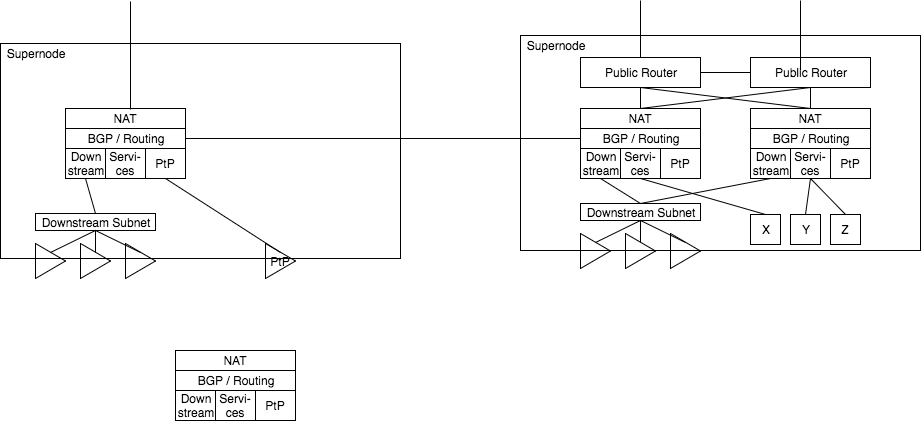 Each supernode has one or more local routers. Each local router has some local subnet, for downstream sector antennas, service nodes, and PtP links. Each router speaks BGP to some of these services and also to neighboring supernodes.
Routers present internet access by passing a NAT layer and consuming some public IP addresses; For example, in a scenario where a single IP connection is handed off, such as Verizon FiOS, the IP is consumed by the NAT services directly.
If the supernode is also a Public Backbone routers, one or more backbone routers provide public access connectivity, with some connectivity being presented to the supernode routers for NAT consumption.
Downstream access can be presented via one or more subnets, one or more antennas, in a mixed fashion for whatever is best for that region.
Each supernode has one or more local routers. Each local router has some local subnet, for downstream sector antennas, service nodes, and PtP links. Each router speaks BGP to some of these services and also to neighboring supernodes.
Routers present internet access by passing a NAT layer and consuming some public IP addresses; For example, in a scenario where a single IP connection is handed off, such as Verizon FiOS, the IP is consumed by the NAT services directly.
If the supernode is also a Public Backbone routers, one or more backbone routers provide public access connectivity, with some connectivity being presented to the supernode routers for NAT consumption.
Downstream access can be presented via one or more subnets, one or more antennas, in a mixed fashion for whatever is best for that region.
Plan to get us to this new architecture
- In our current setup, we present a single subnet directly from our Public Router.
- We should create a second router at Supernode 1 as the supernode router.
- From this new router, we should present several subnets:
- One to Supernode 2
- One to the internal out of band routers
- One or more for downstream client access
- This router should be able to perform NAT for any subnet using a public IP pool
- We should present the Supernode 2 access subnet via a VLAN over the AirFiber 24
- In Brooklyn, we should accept the additional VLAN over the AirFiber and connect it with the router part of the EdgePoint router.
- From there we can setup BGP to accept the routes and also present a default route to Manhattan
- Brooklyn can make several subnets:
- One for internal out of band router access
- One or more for downstream client access
- We can begin to shorten the lease time on the public IPs, switching clients over to private IPs slowly.
- In manhattan, we can begin to use private IPs and public IPs mixed immediately. This subnet will propagate to Brooklyn as well temporarily in-lieu of the Public IPs. As private IPs are found to have no problem, the local private IP subnet can be introduced.
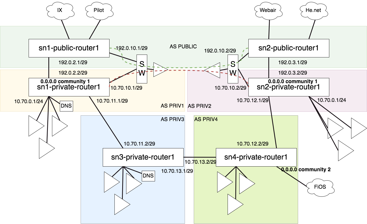
Supernodes interconnecting examples